
Hydraulic energy capture by Kaplan turbine 3/3: the design method
The design method for a Kaplan or propeller turbine starts from two site data, the gross head and the flow rate, and sizes in turn the runner, the distributor, the spiral casing and the draft tube until the head balance closes: gross head = flow path losses + head absorbed by the runner. Two rules guide every choice: minimize head losses, and concentrate the energy in small components. Heliciel carries the whole method in its Hydro Turbine design workshop; this third part of power capture with a Kaplan turbine lays out its logic, which the tutorial works through on a 12 m³/s site.
Hydroelectric turbines chapter:
- Power capture with a Kaplan turbine 1/3: the components and how they work
- Power capture with a Kaplan turbine 2/3: the distributor-runner relationship
- Power capture with a Kaplan turbine 3/3: the design method
- Hydroelectric plant tutorial 1/3: site power and runner
- Hydroelectric plant tutorial 2/3: distributor and spiral casing
- Hydroelectric plant tutorial 3/3: draft tube, balancing and cavitation
Contents of this page:
- Rule 1: minimize head losses
- Rule 2: concentrate the energy to cut the cost of the components
- Capturing the energy: blade lift, torque and swirl
- The balance to reach: head, losses and straightening
- The design phases in Heliciel
1: Rule 1: minimize head losses
On its way down from the upstream reservoir to the tailwater, the water rubs against walls and meets obstacles that take energy from it: the head loss, expressed in meters. The hydraulic energy we want to capture is made of the kinetic energy of the current, ½·ρ·v², and of its potential energy of height, ρ·g·H. The head loss reduces the power as if the head were lower.
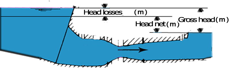
Gross head, head losses, net head.
Three losses are to be avoided: friction losses, losses from velocity changes at section changes, and losses from changes of direction. They are high when the velocity is high on rough walls, when the section changes abruptly, when the direction turns sharply.



To avoid: narrow section, sudden expansion, sharp elbow.
They are low when the velocity is low on smooth walls, when the section varies gradually, when the direction turns gently.


To seek: large section, gradual cone, rounded elbow.
Heliciel computes these losses item by item in Hydro Turbine design: penstock by the Colebrook formula, distributor in four terms, junction pipe, elbow, cone and outlet of the draft tube, after Idel'cik's handbooks. The Mecaflux software remains the general head loss tool for any pipe outside the turbine.
2: Rule 2: concentrate the energy to cut the cost of the components
The price of parts grows with their size: a small runner and a small distributor cost less than a large runner and a large distributor.

To limit the cost of the precious components, runner and distributor, we concentrate the energy in small volumes: we reduce the flow section, and since the flow rate is constant, the velocity increases.
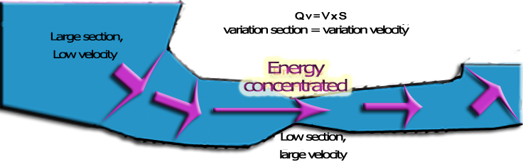
Large sections with low losses, then a "precious" technical zone where the energy is concentrated, through gradual transitions.
The two rules work against each other: the first enlarges, the second reduces. The trade-off between construction cost and efficiency is decided by the payback period and the power of the plant. This is why Heliciel does not set the runner diameter on its own: it proposes it from the specific speed and the ESHA statistics, and you impose it if you prefer.
3: Capturing the energy: blade lift, torque and swirl
The current passing through the runner has an axial component, imposed by the flow rate and the swept section, and a tangential component, the swirl given by the distributor.
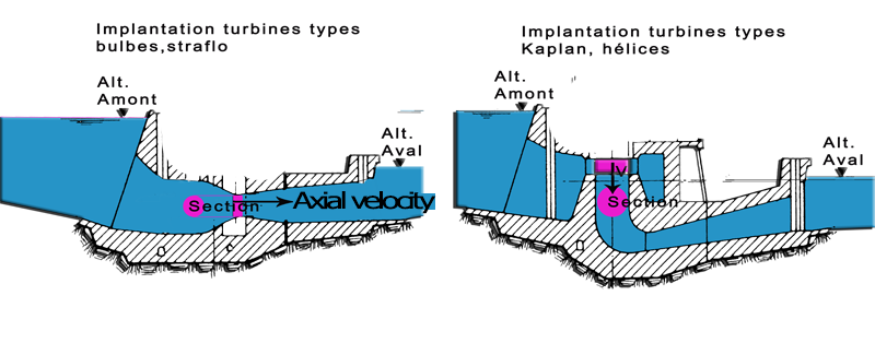
Axial velocity and tangential velocity at the runner inlet.
The swept section is an annulus between the hub and the blade tips: Axial velocity (m/s) = Flow rate (m³/s) / swept section (m²). We control it through the blade root radius and the blade tip radius.
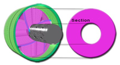
To turn the current into torque, the blades work like wings: their lift, perpendicular to the apparent velocity they see, drives them in rotation. At near-zero speed the lift is well oriented but a lot of water passes through without giving anything up; at high speed it tilts and gives less torque, but less water escapes. There is therefore an optimum speed, which blade element theory computes: this is how every energy-capturing propeller works.
In reaction to the torque, the runner sets the water spinning in the opposite direction: the induced tangential velocity. Any motion that leaves the runner reveals energy that escapes us: this outlet rotation is a loss. The distributor compensates for it by giving the current, in advance, an opposite rotation taken from the head, which the runner converts into torque by straightening the water.
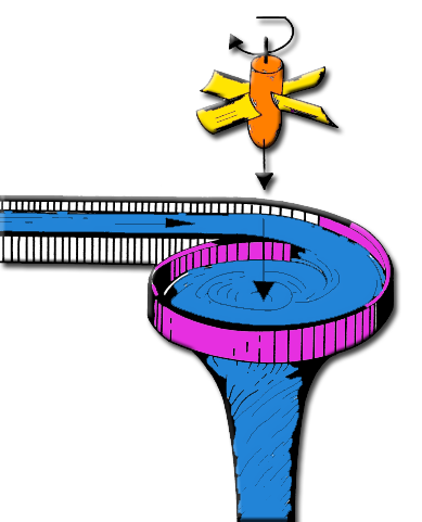
The inlet swirl, which the runner straightens into torque.
4: The balance to reach: head, losses and straightening
In a conduit, the runner does not have to capture a velocity: it absorbs a pressure. The distributor-runner relationship showed it: the net head reaches it in two forms, the static pressure and the rotation that the distributor took from it. The balance is reached when:
- the tangential velocity produced by the distributor and the tangential velocity induced by the runner cancel out, and the water leaves without rotation;
- the head absorbed by the runner, static pressure plus swirl head, and the head losses of the installation together equal the gross head of the site.
This balance ties the runner calculation to that of all the other components. The method therefore consists in computing the runner at the site flow rate, then deducing what the distributor must produce, what the draft tube must recover, and iterating until the balance closes.
5: The design phases in Heliciel
Input data: the gross head (m) between the reservoirs, the site flow rate (m³/s), the supply pipe and the height of the runner outlet above the tailwater level. Results: the rotational speed, the runner (diameter, hub, blades, chords, twist) and its 3D model, the distributor (guide vanes, height, opening, swirl), the spiral casing, the draft tube, the losses of each item, the shaft power and the efficiencies, the cavitation verdict, and the sheet metal kit.
- The site and the specific speed. Head, flow rate and pipe in the Implantation tab; trial speed until Ns falls within the Kaplan range.
- The runner from statistics. Diameter and hub by the ESHA formula or the fleet statistics, number of blades according to Ns, height b0 by equalizing the sections.
- The distributor and the spiral casing. Number and profile of the guide vanes, axis circle, material and velocity of the casing.
- The draft tube. Outlet section for 2 m/s, length for a 14° cone, or your own values.
- Balancing. The solver opens the guide vanes by Euler's equation, computes the runner by blade element theory and adjusts the blade overlap until absorbed head and losses equal the gross head.
- Checking. The piezometric graph and the cavitation verdict, on the flow path and on the blades; if the runner outlet pressure is too low, lower the runner or slow down the speed, and start again.
- The project and manufacturing. The runner is sent to the Heliciel project in penstock mode, with its available head and its upstream swirl; the kit cuts the structure into developed sheets, with the gate ring and the pitch variation mechanism.
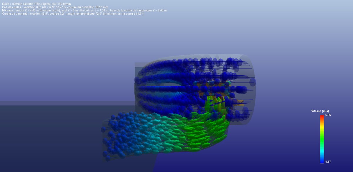
The dimensioned vertical cut, in three-quarter view: the 2,508 mm guide vane axis circle, the 1,868 mm runner, the 766 mm hub, b0, the bulb, the 3,649 mm draft tube, H2 and the 4 m gross head.
Hydro Turbine interface of Heliciel (requires a Mecaflux Suite license)
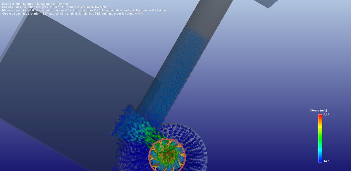
The complete installation, without trajectories: the upstream reservoir at Hb, the penstock, the casing, the distributor, the runner and the draft tube down to the river.
This method can also be carried out by hand, with Heliciel for the runner, Mecaflux for the head losses and a spreadsheet to plot, over a range of flow rates, the head absorbed by the runner and the losses of the circuit: their intersection with the gross head is the operating point. Hydro Turbine design finds this intersection with its solver. To go further, we can work through the tutorial on designing a small hydroelectric plant or read the full user guide of Hydro Turbine design.
 Global site map
 Mecaflux
 Tutorials Mecaflux Pro3D
 Tutorials Heliciel
 Tutorials Heliciel PRO CFD
 Mecaflux Store
 Compare software functions
 Quotes, Orders, Payment Methods
 project technical studies